This is a common and easy project for arduino beginners that can be build in under an hour. The main concept is to create a robot that can follow a line and avoid collisions.
For this project i have used:
- 4 Line Tracker Sensors.
-2 x 5V Relay.
-2 x battery cases (4 batteries x 1.5V each).
-2 x Motors.
-3 or 4 wheels- 2 for the move with the rotors and the others to balance the robot. (in my case i used 3)
-Something to use as the body of the robot (use our imagination! :p ).
-a bunch of wires
- Arduino Uno board.
The Robot:
The wiring is quite easy. To power arduino 2 crocodile wires were used connected with all the 8 batteries. To power the motors 3 batteries are enough, otherwise it will run too fast.
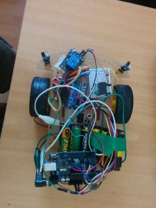
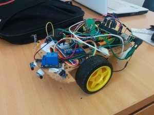
Now, connect the line track sensors to arduino digital pins (in my case 2,4,7 & 8) and place 2 tracking sensors to the front side of the robot. Two sensors will look on the floor in order to “read” the line. These will be the basic inputs for a line follower to work. The other 2 sensors can be put slightly left and right of the robot’s centre so you can add some extra logic to avoid collisions with nearby objects. After placing the sensors take a screwdriver and play a bit with the 4 potentiometers on the sensor’s board. By changing the potentiometers you can adjust the sensitivity of the sensors. For the side sensors you can adjust the distance you want the robot to recognise an object. For the centre sensors you can change the sensitivity to distinguish the line from the floor (this is extremely useful in the case that the floor is not white and it might be consider as a line from the sensors!)
Now that we have set our inputs you have to connect the relays. Relays are used as a switch to stop & start the motors. In this example we are using the motors at one speed only (on/off) so a relay is the perfect switch. for this project you can use any relay of 5V and more. Connect the one end of the relay’s inductor with ground and the other one with an input signal from arduino digital pin (in my case pin 13 for the one relay and pin 12 for the second). Connect the 3 batteries to the relays input voltage and the normally closed (NC) pin to the motor. Also connect the motor’s second pin to ground and that’s all with the wiring!
Below you can see the images of my prototype. It may seem quite messy but is very easy to wire!

* If you want you can add an on/off switch on the arduino battery wire so you can stop the robot whenever you want. I just take the second battery out of the case for this.
The code:
The code is very easy and simple. It was written in arduino sketch and it doesn’t even need extra libraries! So you can just copy and paste or make your own! ![]()
/* Line follower robot Author: Christos Kyprianou Requires: 2 relay 4 line track sensors arduino UNO board 2 motors */ int buttonpin1 = 2; // define tracing sensor pin int buttonpin2 = 4; int buttonpin3 = 7; int buttonpin4 = 8; int found = 0; int rel1 = 12; // define relay pin int rel2 = 13; int val ;// define numeric variables val void setup () { // define tracing sensor output/input interface //pin 2,4 are the center sensors //pin 1,3 are the side sensors pinMode (buttonpin1, INPUT) ; pinMode (buttonpin2, INPUT); pinMode (buttonpin3, INPUT); pinMode (buttonpin4, INPUT); pinMode(rel1, OUTPUT); pinMode(rel2,OUTPUT); Serial.begin(9600); } void loop() { //line track sensors are negative logic //(if line found => output= 1) //(obsticle NOT found => output = 1) int val1 = digitalRead (buttonpin1); int val2 = digitalRead (buttonpin2); int val3 = digitalRead (buttonpin3); int val4 = digitalRead (buttonpin4); //in case no line is found: avoid obsticle mode if (val3 == 1 && val1 ==1){ digitalWrite(rel1,HIGH); digitalWrite(rel2,HIGH); } if (val1 == 0) { digitalWrite(rel2,HIGH); digitalWrite(rel1,LOW); } if (val3 == 0){ digitalWrite(rel1,HIGH); digitalWrite(rel2,LOW); } if (val1 == 0 && val3 ==0){ digitalWrite(rel1,LOW); digitalWrite(rel2,LOW); } //when line is found: line follower mode if (val2 == 1 || val4 == 1){ line(); found = 0; } } void line() { //line follower mode int val1 = digitalRead (buttonpin1) ; int val2 = digitalRead (buttonpin2) ; int val3 = digitalRead (buttonpin3) ; int val4 = digitalRead (buttonpin4) ; while (val4 == 1 && val2 ==1){//Black line is found val1 = digitalRead (buttonpin1) ; val2 = digitalRead (buttonpin2) ; val3 = digitalRead (buttonpin3) ; val4 = digitalRead (buttonpin4) ; if (val1 == 1 && val3==1) { digitalWrite(rel1,HIGH); digitalWrite(rel2,HIGH); } if (val1 == 0) { digitalWrite(rel2,HIGH); digitalWrite(rel1,LOW); } if (val3 == 0){ digitalWrite(rel1,HIGH); digitalWrite(rel2,LOW); } } while (val2 == 0) { digitalWrite(rel2,HIGH); digitalWrite(rel1,LOW); val1 = digitalRead (buttonpin1) ; val2 = digitalRead (buttonpin2) ; val3 = digitalRead (buttonpin3) ; val4 = digitalRead (buttonpin4) ; if (val1 == 0) { digitalWrite(rel2,HIGH); digitalWrite(rel1,LOW); } if (val3 == 0){ digitalWrite(rel1,HIGH); digitalWrite(rel2,LOW); } } while (val4 == 0){ digitalWrite(rel1,HIGH); digitalWrite(rel2,LOW); val1 = digitalRead (buttonpin1) ; val2 = digitalRead (buttonpin2) ; val3 = digitalRead (buttonpin3) ; val4 = digitalRead (buttonpin4) ; if (val1 == 0) { digitalWrite(rel2,HIGH); digitalWrite(rel1,LOW); } if (val3 == 0){ digitalWrite(rel1,HIGH); digitalWrite(rel2,LOW); } } line(); } |
The Result:
The result of the project is shown in the following video!
Hope you enjoy it! ![]()
As soon as your prototype works you can always make some changes and have some fun!!
